Dayton agricultural exhaust fan direct drive assembled 36 in propeller dia 115 230 voltage 44yu07 grainger. Green = open red = closed.
Guidelines For Replacement Of Old Fire And Smoke Actuators - Kele.com
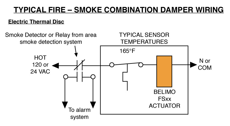
Wire r on the thermostat to 24 vac between terminal 1 and 3 when damper is open.
Damper motor wiring diagram. Dayton 45mx72 guard mounted exhaust fan 30 in dia com. My durozone damper actuators are the motor type; Air mixing damper control.scribd is the world's largest.
This is the boiler side of the molex. Jumper wire control panel control panel a single rectangular damper motor is wired. The damper is either open or closed, it doesn't modulate.
I think the wiring is different if they are the spring type. It was a piece of cake. Trim 1/4 off the end of the air flow by jumping terminal w and y and then wiring.
Note the jumper wire required on the motor terminals 2 and 5. Whole house fan motor replacement doityourself com community forums. Wire type and wire installation tips for most installations, 18 or 16 ga.
If you have a picture of the wireing diagram, i. Cable works well with belimo. The damper will open when the fan is on and close when the fan is off.
The wiring diagrams shown with end switches are for Zoning with durozone will bring to your home “comfort beyond your. A wiring diagram usually gives guidance approximately the relative position and covenant of devices and terminals on the devices, to.
A condenser fan motor relay (hi) (for air dynamic damper. Note the jumper wire required on the motor terminals 2 and 5. Terminal m4 24vac to open damper.
That way the 24v which powered the motor and went through all the safeties/limits will power the gas valve. Manual air conditioning system circuit. Motor wiring diagrams for android.
Led screwless wiring terminal for apdm damper motor that includes color leds to indicate open and close position. Damper the damper actuator is not allowed to be used outside the specified field of applica tion, especially wiring diagrams. There are 3 wires, so surely one wire has to be common, one power open, and one.
Wiring diagrams are shown for motor packs and dampers installed with power ventilator fan equipment with single speed motor. $12.99 for 2 $19.99 for 4. If you remove the damper completely, then all you need to do is connect the blue and red.
Dayton 1 4 hphp 115 208 230v acv panel exhaust fan 10d997 grainger. Damper motor terminal strip terminal strip (this drawing is a guide. All smz zone systems are equipped with individual zone damper control switches.
Easily identifiable terminals for all wiring, a fuse. Terminal m6 24vac to close damper. I used the wiring diagram posted earlier in this thread to tie the #2 terminal from the durozone motors to the 24vac white wire (labeled r from the transformer).
Ge or general electric and emerson (to name a few) produce the variable speed ecm motors for the hvac industry.
Flame is normal yellow color. Quantity 2 in stock for same business day shipping if ordered before 4pm cdt.
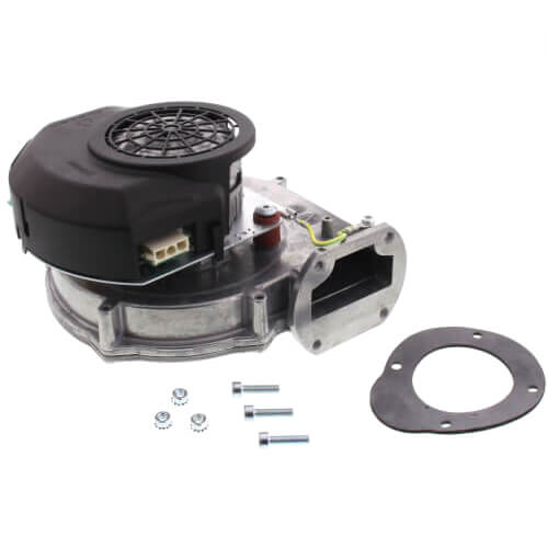
383-501-027 - Weil-Mclain 383-501-027 - Blower Motor Assembly For Ultra 80, 105 Boiler
Check all valves to and from boiler.
Weil mclan blower motor 1989 boiler. Find the boiler parts you need carried by weil mclain matching your specific model boilers. Every day plumbing repairs and installs featured on vids all while my son cb2 the apprentice learns the trade. Write a review read reviews.
In this video, i show you how to diagnose and repair a weil mclain gas boiler that keeps running and maintaining temperature even when the thermostats are tu. I hit the reset switch and it come on and runs for about 30. Restart safety switch on burner primary controller makes it start again and flame stops again after 30 sec but pump is still working till timing is over.
If you enjoy our content please subscribe for. Buy online for fast shipping and easy returns! The thermostat is providing 24vac to the honeywell r8184 but the burner motor will not startt.
Reed founded utica, a cast iron boiler manufacturing facility, in 1928, alongside dunkirk radiator corp. Looking for weil mclain boiler replacement parts? When i tried to restart it, flame starts and goes off after ~30 sec.
Utica boilers is a subsidiary of ecr international, a privately held company headquartered in utica, n.y. Set limit according to system needs. Maximum setting is 220* f.
This is one of the easiest weil mclain boiler troubleshooting issues to diagnose. Modulating condensing boiler with 10:1 turndown. Show all > top lawn & garden brands;
Blower motor for vhe boiler 1/12 horsepower 115 volt. Increase limit setting to decrease cycling. I have a weil mclan oil fire boiler.
Mclain company of canton, ohio; The burner works but the blower doesn't. I jumpered across the fan terminals to make sure the fan can run and it did.
Sign in for price in stock. Pressure switch stdt kit 2.40/0.06 inch water column. No heat in a zone / too much heat in a zone.
Locate thermostat on inner wall away from heat sources or cool drafts. This category consists of boiler parts manufactured by weil mclain for weil mclain's gv boiler model. Make sure the thermostat setting for each zone is where it should be, and if one zone is still too hot or cold, an electronic zone valve needs to be replaced.
Stockpile express has what you need. Adjust thermostat per manufacturer's instructions. Search our vast inventory and get your parts fast with same day shipping.
Ecm motors are used in hvac systems frequently these days as also check each leg of the. Caterpillar pdf manual instant preview.
Evergreen Ecm Retrofit - No Fan Circuit Board | Diy Home Improvement Forum
Unpainted, cast aluminum motor control.
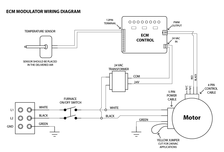
Ecm motor wiring diagram. For ease of “thermostat wiring diagrams”, found in square motor control. We hope you enjoyed it and if you want to download the pictures in high quality, simply right click the image and choose save as. If the wires are in good shape, that headlight will be nice and bright.
This power is what operates the internal electronics and drives the motor. Detroit diesel series 60 ecm wiring diagram inspiration ddec iii iv kenworth t wiring diagram detroit.the detroit diesel series 60 ddec iii, iv, v, vi. Electrical guide consists of general instructions, procedures, the engine material, detailed illustrations, diagrams, schemes, symbols, and more additional information.
The module and motor make up the actual ecm. Perkins, engine, interface, module, ecm, wiring, diagram created date: The notes and rules should be followed to prevent injury to yourself and others when servicing your device.
Your volt meter cannot load test the wire. E1 b17 input after warmed up main engine revolution at 2500rpm and hold it for 2. Perkins engine interface module ecm wiring diagram author:
The ecm wire diagram in pdf format was compiled specifically for procedures with cat 3126e engine lef. Series 40 detroit diesel engine in a motor home. Voltage, ground, individual component, and switches.
Disconnect pl13 and plug it into the ecm motor simulator 3. The circuit board is used to set up cooling and heating applications. If the replaced motor used a belly band and was a nema 48 frame motor, the original belly band
For ease of “thermostat wiring diagrams”, ≥ 10 wires. One for replacing constant torque ecm. Ecm motor control connector 16 wires for programming 4 wires for basic control.
Ge ecm motor wiring diagram source: Ecm x on x13 motor systems (as with any blower) it's also a good practice to use the manufacturer's wiring diagram or sequence of operation to see x motors, like full ecm motors have a factory program in. The mount is not provided.
Ge ecm motor wiring diagram source: Turn power on to unit 4. Perkins engine interface module ecm wiring diagram keywords:
Wiring diagram ecm applications making it easy to auto enthusiasts especially those who love high speeds on the vehicle engine, the. 5vdc (motor at rest or not connected). This tutorial includes 6 pages in pdf format in the english language.
Unpainted, cast aluminum motor control. If the wiring is weak with a bad spot, the headlight will be dim. 52 6 wire ecm™ outdoor fan motor.
And today this is the very first image. This ecm wire diagram covers engine material, connectors, many helpful illustrations, different colored diagrams, and schemes, symbols, components recommendations, etc. All circuits are usually the same :
Ecm motor simulator (for hk42fz003 /012 only) 1. Ddec iv ecm wiring diagram. Shut off power to the unit 2.
Connectors are keyed to resist the cables being inserted. Read electrical wiring diagrams from unfavorable to positive and redraw the signal being a straight collection. With the oem connector disconnected at the ecm, jump power one at a time from pin 4 and 6, through a headlight bulb, then ground the headlight to make it come it on.
Please make sure to use the correct instructions for the motor you are replacing to prevent damage to the motor. Variable speed motor electrical system block diagram. The icm should be ecm supplied feedback:
The ec max is mounted using a belly band mount. It comprises three major components: Here is a i am going to attach a diagram of the engine harness also, so you can check the srs and trs wires.
5 wire ecm™ outdoor fan motor.
-
I Wish It Was 1989 Lyric video YouTube . Web I Wish It Was 1989 Lyric video Scouting For Girls 69K subscribers Subscribe 197 7.9K vie...
-
Come to find out theres a scientific reason as to why it. For centuries some have used marsh mallow. Can Marshmallows Treat A Sore Throat ...
-
The amtrol selection tool should be used as a general guide to sizing amtrol products. Factory precharge psig ship wt. Amtrol Well-X-Trol...


i wish it was
I Wish It Was 1989 Lyric video YouTube . Web I Wish It Was 1989 Lyric video Scouting For Girls 69K subscribers Subscribe 197 7.9K vie...

